FPGA and MCU Setup and Testing
Intro & Design Approach
In Lab 1, the tasks included assembling the E155 protoboard, verifying the functionality of the MCU and FPGA, controlling a 7-segment display, and controlling onboard LEDs using SystemVerilog with Lattice Radiant. The lab was completed in approximately 8 hours.

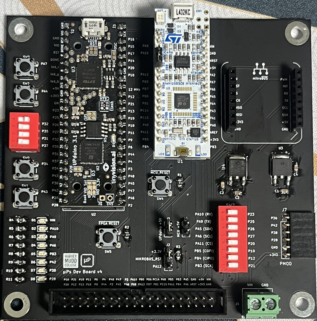
Micro Ps Protoboard
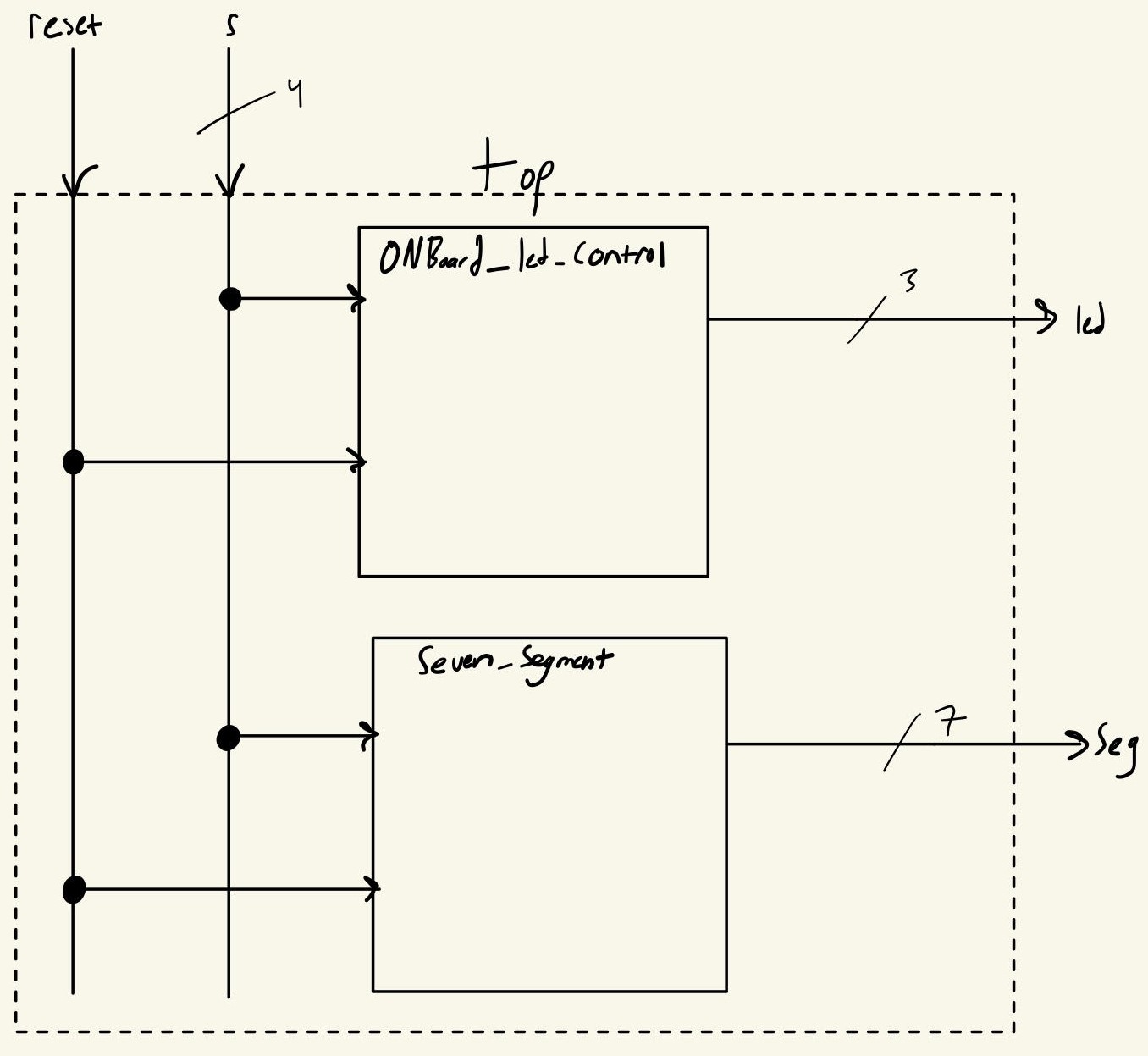
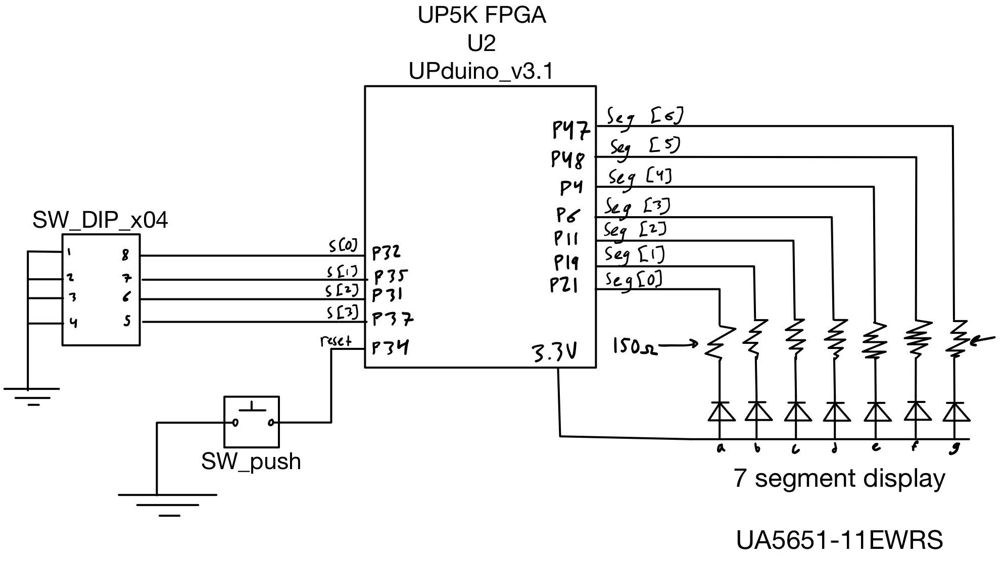
After following the setup instructions from resources/E155 (Micro Ps Course Website)/Lab 1, a block diagram and circuit schematic was created to outline the SystemVerilog modules and signals for implementation. This step facilitated organization during the coding process.

Block Diagram
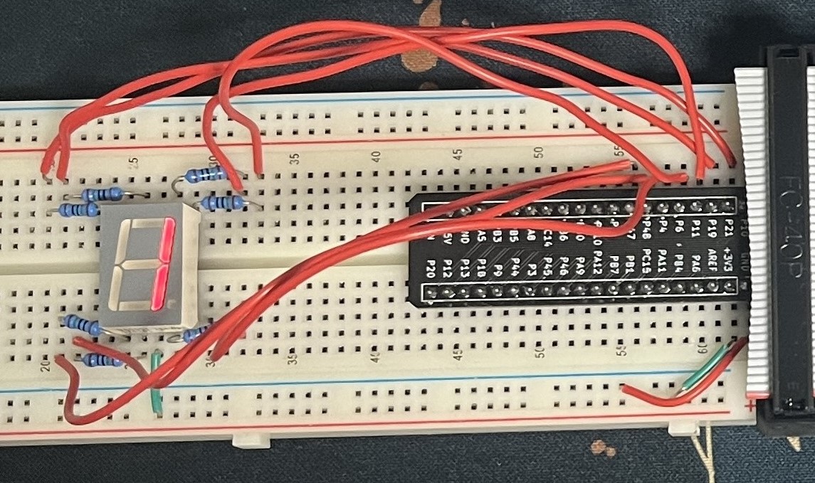
This lab involved implementing combinational logic for DIP-switch inputs, with a single 7-segment display showing hexadecimal digits (1-F) based on those inputs. Combinational logic blocks were implemented using case statements for XOR and AND operations, with outputs displayed on the onboard LEDs. The high-speed oscillator (HSOSC) was used to oscillate another onboard LED at approximately 2 Hz. Additionally, a case statement was used for the 7-segment display output, and pin assignments were meticulously configured in the device constraint editor in Lattice Radiant.

Circuit Diagram
For troubleshooting and debugging, manual test cases were used to verify that the correct segments illuminated as expected. A multimeter was also employed to ensure pins were functioning properly. These steps facilitated tracing issues to the software and effective code debugging.

Results & Reflection
The design meets all the lab requirements at an acceptable level. However, accuracy in the LED oscillation could be improved. Currently, the LED oscillates based on the 25th bit of the high-speed oscillator (HSOSC), resulting in an approximate frequency of 2 Hz instead of the specified 2.4 Hz. To address this, a second counter could be implemented to track the exact oscillations from the HSOSC and adjust the LED to precisely 2.4 Hz.
I particularly enjoyed learning how to use Lattice Radiant, as it helped me reconnect with SystemVerilog concepts I had learned over a year ago in E85.
Moving forward, I will be more meticulous about reviewing and commenting my code. My initial Verilog code lacked sufficient comments, leading to confusion within the submodules.